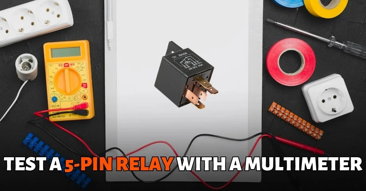
A 5-pin relay is an electromechanical device that uses an electrical signal to control a high-current circuit. Its main purpose is to switch power from one circuit to another, enabling or disabling the current flow. It is commonly used in automotive and industrial applications to control systems such as motors, lights, and fans.
To ensure the efficient functioning of a 5-pin relay, testing is crucial. The primary purpose of testing a 5-pin relay is to determine whether it is functioning correctly or not. This can help prevent system failures, which could have severe consequences, including equipment damage, injury, or even death.
Using a multimeter to test a 5-pin relay is crucial as it allows for accurate voltage, resistance, and continuity measurement, providing valuable information about the relay’s condition and performance.
Understanding the 5-Pin Relay
A 5-pin relay consists of several parts that work together to control the flow of current. Each pin of a 5-pin relay serves a specific function. They are:
| Pin Number | Description |
|---|---|
| 85 | Coil |
| 86 | Coil |
| 87 | Normally Open (NO) |
| 87a | Normally Closed (NC) |
| 30 | COM |
Pin 85 – This is the coil ground terminal that is connected to the chassis or ground.
Pin 86 – This is the coil-positive terminal that is connected to the control circuit.
Pin 87 – This is the normally open (NO) contact terminal that is connected to the load.
Pin 87a – This is the normally closed (NC) contact terminal that is connected to the load.
Pin 30 – This is the common (COM) terminal that is connected to the power source.

When a current is applied to the coil, it generates a magnetic field, which pulls the switch contacts open or closed. This action opens or closes the circuit, allowing or stopping the current flow. The relay can be used to control a high-current circuit using a low-current signal, making it a valuable component in many electrical systems.

Preparing to Test a 5-Pin Relay
Before testing a 5-pin relay, it’s important to gather the necessary tools and equipment. These tools will ensure that the testing process is accurate and efficient. Here are the tools and equipment you will need:
- Multimeter
- Relay wiring diagram
- 12v charged battery
- Jumper wires
By gathering these tools and equipment, you can ensure that the testing process goes smoothly and accurately. Once you have everything you need, you can move on to identifying the type of 5-pin relay you have and understanding its wiring diagram.
How To Test a 5-Pin Relay with Multimeter
To test a 5-pin relay using a multimeter, set the multimeter to measure resistance and connect the probes to the 85 and 86 pins. If the meter displays a resistance reading between 50Ω and 200Ω, the relay coil is good. Activate the relay using a 12-volt battery and jumper cables, then measure the resistance between pins 30 and 87. A reading between 0.2Ω and 0.5Ω indicates that the circuit is working properly.
Let’s discuss this in more detail..
STEP-1
First, to get accurate results, you need to set the multimeter to measure resistance by putting it in the maximum Ohms setting, which is 200Ω. Ohms is typically represented by the meter’s Omega symbol (Ω).
STEP-2
Then, connect your meter probes to the control circuit pins, usually labeled “85” and “86”. If the relay coil is in good condition, the meter will display a resistance reading between 50Ω and 200Ω, depending on the relay model. If the meter shows a value outside this range or “O.L”, then there might be a broken circuit within the relay or a problem with its coil. In this case, you should replace the relay.
STEP-3
If you get a good reading on the control circuit pins, you can test the resistance between the 30 and 87 pins. But first, you will need to activate the relay. To do this, you’ll need a 12-voltage battery and jumper cables. Supply power and ground to the 86 and 85 pins, respectively. You should hear a click sound when the switch activates from 87a to 87. If you don’t hear it click, toss the relay because there’s no point in going any further. However, even if you hear it click, you need to go further and test the relay to be 100% sure it’s a good one.
STEP-4
Measure the resistance between 30 and 87 pins. Make sure your multimeter is still in the Ohms setting, and then touch the pins number 30 and 87, which are going to be these two pins, and get your measurement. The circuit is expected to be activated at this point, and the meter presents values between 0.2Ω and 0.5Ω, which is really no reading at all, pretty much zero resistance.
By following these steps, you can accurately test a 5-pin relay with a multimeter and ensure that it’s functioning correctly. It’s essential to be thorough when testing relays to avoid misdiagnosing issues and wasting time on unnecessary repairs.
Conclusion
In conclusion, testing a 5-pin relay with a multimeter is a simple process. The first step is to identify the pins on the relay and then use the multimeter to check for continuity between them. If there is no continuity or an open circuit, the relay must be replaced.
Ensuring that your multimeter is set correctly for testing resistance and continuity during this process is important. Additionally, follow safety precautions, such as disconnecting power sources before beginning electrical work.
Understanding how to test a 5 pin relay with a multimeter can help troubleshoot issues with your car’s electrical system and prevent costly repairs down the line. Following the above simple steps, you can easily determine if your relay is functioning properly or needs replacement.


